Hi all,
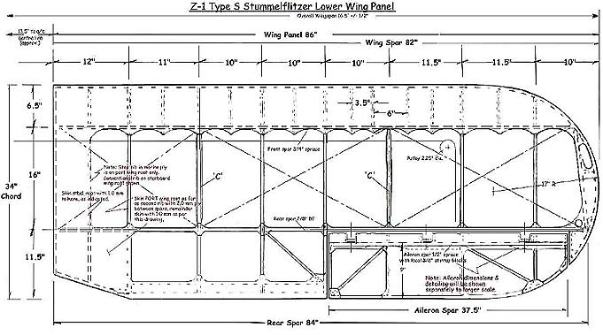
I have just finished doing the drag wires on my lower wings and have kept a photographic record of the process to hopefully save others some time. Please note that what I have used is 13swg (equivalent) which is not applicable to all Flitzers. The principles remain the the same however.
Regards
Duds
What follows will be too detailed for the experienced builders amongst you but since being involved in the Flitzer scene I have realised that there are some first time builders who appreciate as much help as they can get.
We all know that there are several ways to skin a cat. An earlier group discussion on doing drag wires again demonstrated this. Out of all the ideas I developed the following system for my build. It appears to be satisfactory and relatively easy to achieve.
I had got quite well into this system of using nicopress sleeves on hard wire, something that they were not designed for, before I was told that there was a non-stretch cable available. I had gone too far though and didn’t look into it.
I think that Lynn’s idea of using solid wires was to obviate the need for a zillion access points under the wings for access to re-tension cables had they been used. It is true that the aircraft would have looked like a cheese, and the re-tensioning would not have been easy job either.
Using the method described below I found by experimentation that each of my wires ‘stretched’ by exactly 5.5mm (0.22") when a pulling force of 690kg was applied to them. I had done both short and long samples to test ‘stretch’. As both grew by the same amount it was obvious that the wires were not stretching, but the wire was slipping around the thimble. I used 690kg as a benchmark as evidently the inboard wires need the ability to take 650kg maximum.
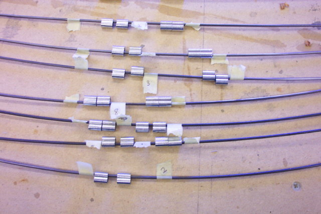
Please note that for ease I have used 13swg wire throughout, this is not the size usually used in other Flitzer models but the principles will apply.
For this recipe the following is required:
| 3lbs music wire - Aircraft Spruce part No 03-49600 .090" |
| 96 MS51844-23 3/32" nico press sleeves Aircraft Spruce part No 28-2-G |
| 48 AN100C4 3/32" thimbles |
The 3 lbs of wire includes spare for experimentation but the other two quantities do not, so add a few thimbles and a dozen or so sleeves to above.
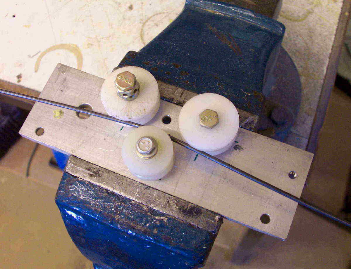 |
This photo shows my crude wire-straightening tool. It was Chris Bobka who reminded me of how this was done. The central grooved nylon bobbin is bolted through a slot in the base plate so its position may be adjusted to give the correct straightening effect. |
 |
The next stage is to very accurately measure bracket hole center-to-center of each wire position. I used two pieces of piano wire side by side, taping them together after positioning with ends centre of holes, removing from wing and measuring. |
 |
From the dimension arrived at above, deduct the hole center-to-center length of a turnbuckle (mine are about 130mm (5.1") at mid-adjustment) and cut the wires about 250mm (10") longer than this new dimension. Clean wires with thinners to remove oil film, then lightly abrade with medium scotchbrite. Number each wire, slide on two nicopress sleeves from each end and lock on with a tag of masking tape. I know it is not necessary to put the sleeves on yet but doing it now, to all wires, avoids the embarrassment of bending the second end with sleeves on the wire. (I know). |
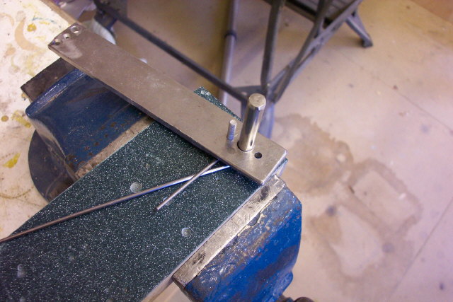 |
This shot shows very homemade, but effective, wire bending tool. Into the worktop material base is fitted a 3/8"dia pin and adjacent to it is an 8swg pin protruding by about 3mm (1/8"). The bending handle has a 3/8" plus hole with a projecting pin positioned the wire diameter plus say 0.4mm (1/64") tolerance from the edge of the hole. |
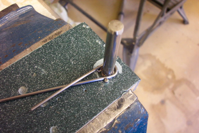 |
Lay a wire in the tool with about 100mm (4") projecting past the pin. Place handle in position and rotate. Check shape against a thimble to get somewhere near. |
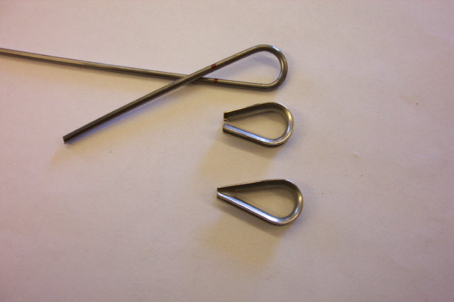 |
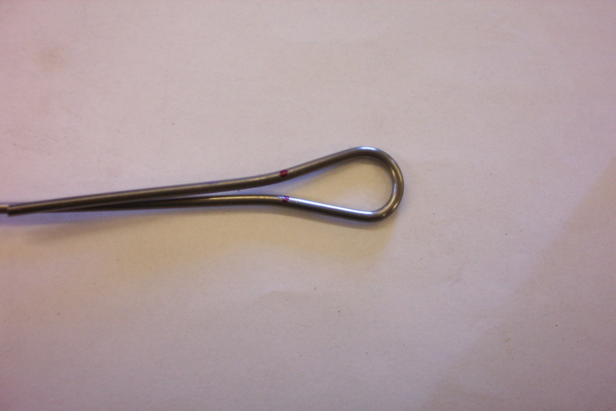
Grind the points off the thimbles as shown and mark the bend positions on the wire. I think it was ‘down-under’ Mark that came up with this one. |
 |
|
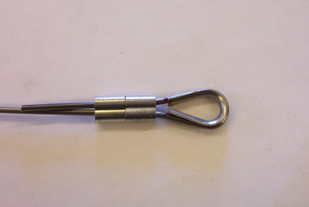 |
Put the thimble in place and slide nico sleeves up as far as possible. |
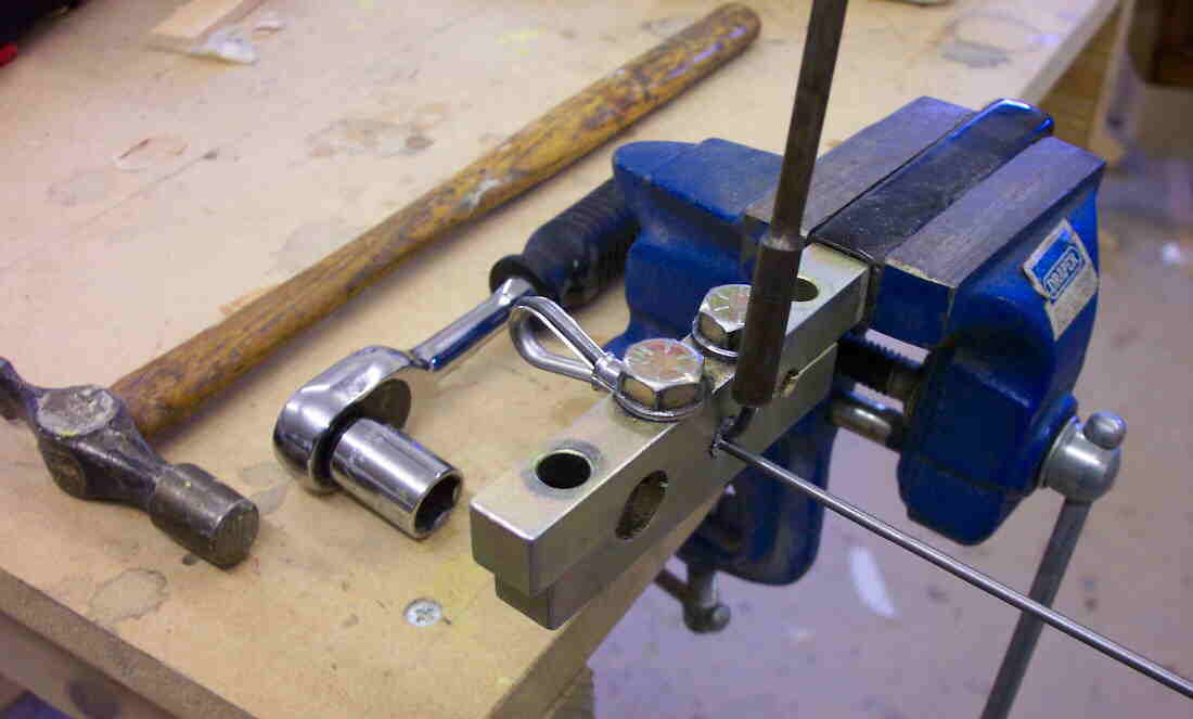 |
Place the sleeve closest to the thimble in the nico tool and compress it until it is just gripping the wire. The trick then is to tap the end of the wire (hence the pin hammer in this shot) to move the wire loop and thimble as tight to the sleeve as possible. When satisfied tighten down tool, alternating between bolts to keep the jaws as parallel as possible. It is important to get as tight a clamping action as possible. Then place the tool on the second sleeve and by the same method get the two sleeves touching. After tightening the second sleeve, and before removing the assembly from the tool, bend up the free end of the wire. A small tube over the wire aids this process. I used a 6BA nut runner as seen in the photo. |
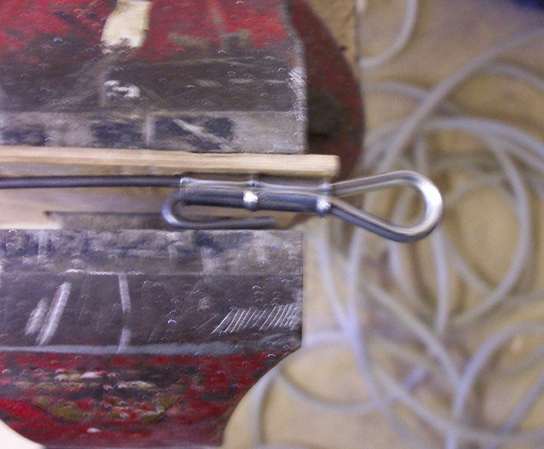 |
Place in vice and squeeze up. Note ply protector in vice. |
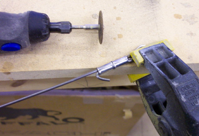 |
A Dremel tool with a cutting disc is a very useful item in the workshop. |
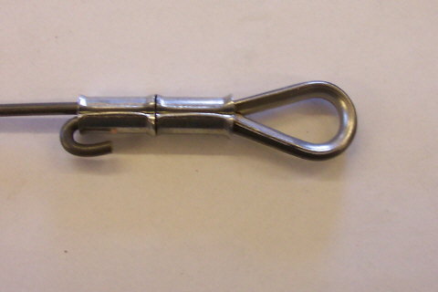 |
Finished end ready for ‘stretching’. |
 |
Obviously half of the wire ends are going to be attached to a bracket, unless you use shackles. Using shackles is easier but heavier and more expensive. Experimentation is needed to establish where to mark your wire for the second end to be in exactly the right place. I found that on my bending tool if I put a mark on the wire, and put that mark where the wire touched the little restraining pin. The inside of the thimble would end up 8mm from the mark. So with a little simple arithmetic you should be able to establish exactly where to mark all your wires. List all these dimensions; knock a nail in the workbench over which to loop the thimble of the finished end, and lay the wire out alongside a rule clamped to the bench. The end of the rule being flush with the outside edge of the nail. Now work through the wires marking the lengths appropriately. Bend wire ends and when at the stage shown in Drag 7 photo, slip the thimble through the hole in the bracket, feed the wire through the bracket hole going along the groove of the thimble and position the thimble in the wire loop. Clamp up the sleeves and finish the end all as before. |
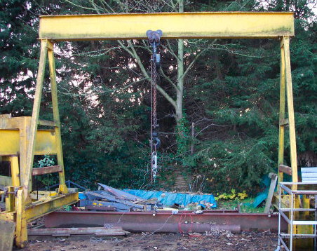 |
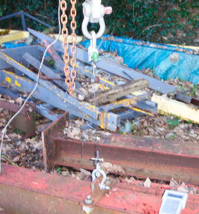
The rig that I had access to via Bill Sherlock, a friend well known in the microlight world. You can see the load cell hanging from the endless chain block and tackle. As an alternative one can make a cable tester by screwing down a dexion angle from one end of which is hinged a very unequal L of angle iron. If there is a hole, say 1" vertically above the hinge bolt to which to attach one end of the cable, and a horizontal angle iron running horizontally from the hinge for say 60", one can see that a 60:1 advantage is gained. A know weight of water, or anything else handy, can be added to the end of the horizontal member so straining the cable that is attached to the hole 1” from the hinge bolt and a convenient hole somewhere along the dexion. One has to remember to allow for the cable strain attributed to the weight of the angle with this method. |
 |
The business end. A not very clear shot of a wire in the process of being ‘stretched’. Many shackles reducing in size are required to get down to fit a little job like this. |
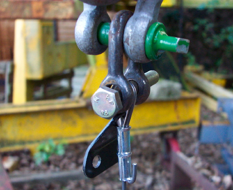 |
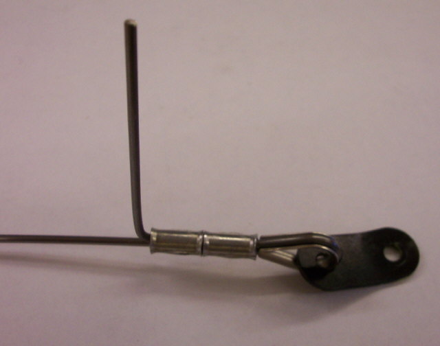
The bracket end of the cable in the shackle. It was found that a 8mm (5/16") bolt would just pass through if the thimble hole in the bracket was drilled with a number 8 (.199") and then lightly countersunk to remove the sharp edge. The bracket would then just have enough free movement to allow it to be moved out of the way. |
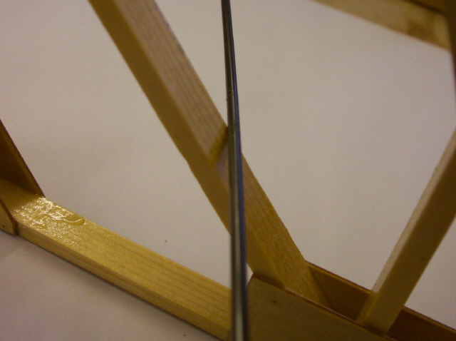 |
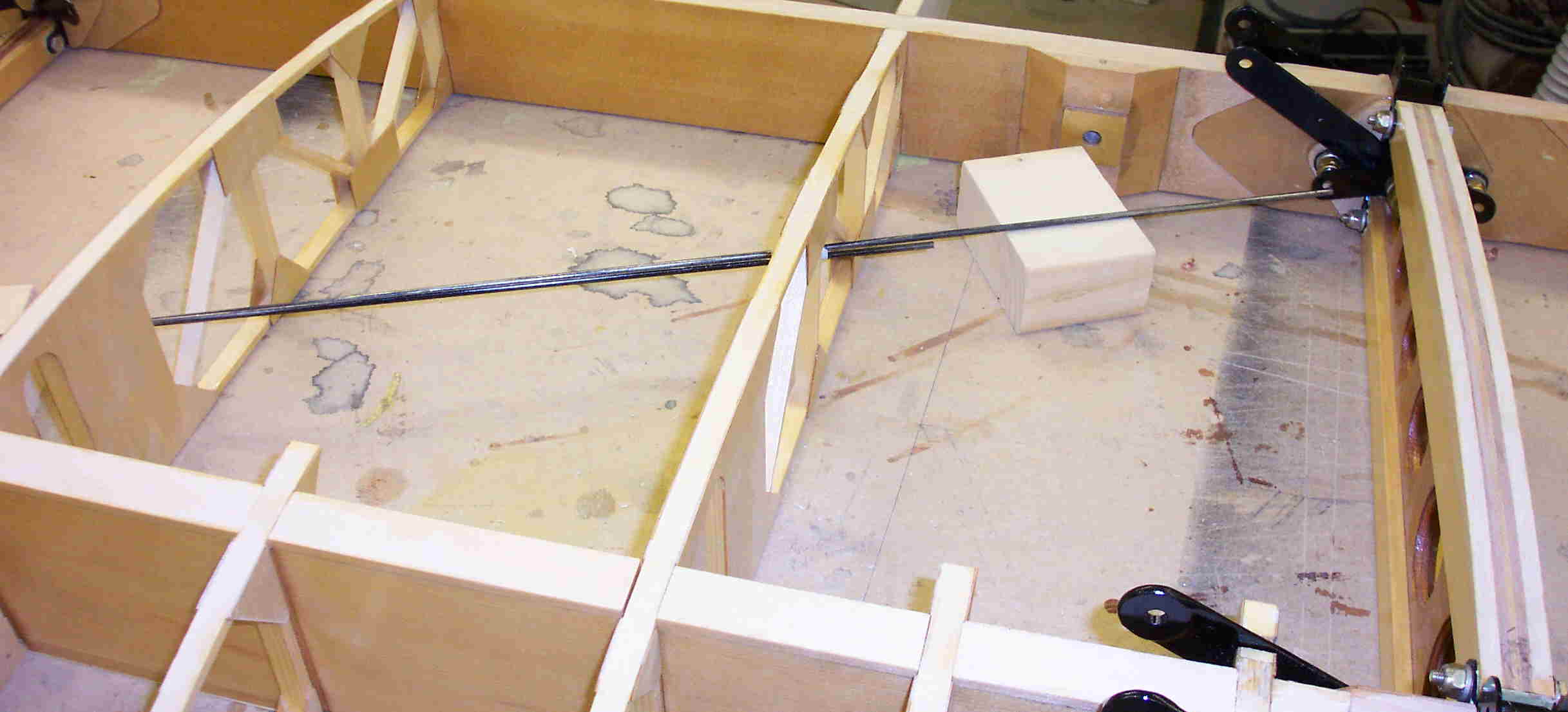
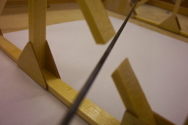
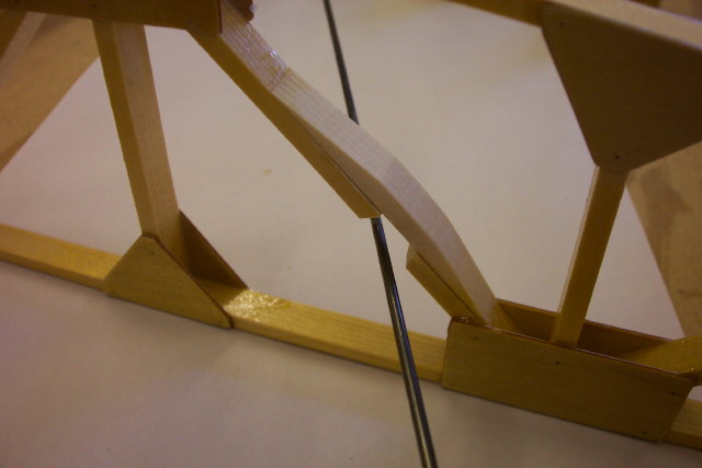
A few photos that show how to get over a clash between rib and drag wire. If the wire is close to a rib, but not touching use a bit of waxed cord to tie to the rib to prevent 'buzz'. Wax cord also used where the wires cross each other. |
 |
|
 |