
1/ If desired, some sections of the outer skin may be glued to the fuselage prior to assembly (see small sketch on #Z200), but it is easier to work on the fuselage as an open structure. Set up fuselage sides parallel on bench with 'string laser' (black cotton thread) stapled on benchtop centre-line, and glue short, one piece hardwood inside-longeron doublers at STA-2 . See bottom of sheet #Z110 for modification to cut-out in STA-2 carry-thro'.
2/ Mark firewall centre line, dry-fit firewall onto projecting longeron forward ends, and drop STA2 & 3 carry-thro's into place on lower longerons to assist in squaring-up forward fuselage. These joints should be reasonably tight. Trammel structure. Pack up rear fuselage near stern with scrap timber to level structure and prevent movement. Do not bring fuselage rear sections together yet as this will tend to bow forward fuselage.
3/ Check for vertical on sides and place level across upper longerons. Glue firewall in place, trammeling before tightening sash-cramps across forward fuselage. When dry, glue forward cross-members in upper and lower longeron planes against rear of firewall (STA-0) and gusset upper member when dry. (Note: use Stummelflitzer Drg. here.) Working rearwards, cut upper and lower cross-members for STA-1 in forward fuselage; upper, pre-fabricated and drilled for fuel tank-strap attachment, and lower, step-modified for heelboards (#Z110) and glue in position, together with pre-drilled and ply-gusseted carry-thro's at STA2 & 3, when satisfied that fuselage is true. Pay particular attention to correct alignment and trammeling of carry-thro's. Glue 45 deg. triangular 9/16" spruce or Douglas fir (ply-backed) engine mount backer where indicated on #Z202.
4/ Pre-fabricated, pre-painted, 14 SWG. secondary lift-wire truss tie-member, Z-202-9 Mod. is laid in position (qv. notes on #Z206, ie. temp. cutting away of vertical to allow ingress of fitting) and screwed to STA-2 carry thro' upper edge with brass screws, and parts Z107-1 &-2 are bolted onto appropriate STAs., using Duralac where necessary.
5/ When dry, with all lower fittings in place, glue 7/8" x 5/8" vertical compression inserts (pillars) into space between paired uprights, ensuring tight contact at lower end of compression pillar. Make good any cut away section of upright necessary for fitting access and when dry, fit internal (1mm.) vertical plywood gussets at STAs 2 & 3.
6/ Glue pre-laminated bow, associated gusset blocks etc. at end of STA-2 and similar gusset/blocks at STA-1.
7/ Add 2mm ply stress-tray. Heel board support structure, etc, in lower fuselage is best added at this stage. Add seat-beam/torque shaft support-member at STA-2A. (at rear end of hardwood doubler).
8/ Build up cockpit seat-support structure at cockpit rear to upper longeron level. When all is dry, pull rear fuselage together at rear and tie lightly. Using suitable straight timber section (eg. 2" x 1" as doublers, clamp these to all longerons to ensure that rear fuselage maintains a straight taper at approx. 8 degrees to sternpost, planview curve occurring between STAs-3 & 4. Steaming should not be required, but do not use excessive force if 'dry' bending.
9/ At this stage skin seat back support with 2mm. Gaboon or 1.5mm or 2mm. birch ply. An access door is strongly recommended, as shown on #Z206. Attach sternpost, and add all remaining cross members, diagonals, etc, ensuring symmetry in all planes, glueing blocks where appropriate, and gussets. Build-in elevator-pulley 'V'-frame structure at STA-4, ensuring that the lowest longeron cross-member at this point is displaced 1" to the rear to ensure cable clearance. Invert fuselage, and glue 2mm. forward floor section in place from firewall to STA-4. Fit dorsal seat doublers, with blocks and gussets glued to inside surface of lower ply skin (floor). Luggage locker ply deck can now be added, together with harness brackets. Note that there will be an improved (three-bolt) shoulder harness restraint fitting and upper fuselage cross-member drg. issued (qv e-mail attachment).
10/ Skeg (tailskid support structure) is built as an independent unit, and offered up to the rear fuselage virtually complete. Ply diaphragm, additional blocks and filler blocks, etc. are built into the fuselage rear when the now rigid fuselage has been inverted. Ensure that otherwise inaccessable anchor nuts for the fin post attachment and rudder hinge, internal fore-and-aft tailplane spar supports, rudder cable (neoprene) guide tube clips, etc., are fixed prior to boxing-in these sections. Ensure that cable run cut-outs are fretted through ply diaphragm.
Note that longerons are 'stepped' and re-inforced to accommodate the forward tailplane spar, and that a rear spar mounting block is glued to the curved ply tailplane-deck section ahead of the sternpost. The rear fuselage, ply outer skins, when applied, should be swept upward locally to protect the end-grain on this rear block, as shown on #Z200, 201, etc.
11/ The entire fuselage may now be boxed-in, ensuring that suitable access ports are provided. Carefully drill and ream through STA-2 carry-through external stub-end and Z-202-9 for vertical attachment bolt for part no. Z209-3/4 (upper, rear undercarriage leg attachmt.) and fit forward truss 14 SWG pick-up, Z202-6 . Refer to #Z-107 for ply packing details at STAs 2 & 3., items 12, 17, & 20. Fit lower torso restraint brkt.& washer plate, Z200-1/2&3.
12/ Build-up stub ribs at 1.5 degrees incidence on fuselage sides for wing root-fairing screw attachment, this will conceal the lower harness washer plate. This completes the primary structure to fully-skinned stage. Forward and rear decking laminations, and skinning follow a separate schedule, and information will be provided on this on request.
Best wishes,
Lynn
It might be worth incorporating an anti-stress riser, a tapered doubler just aft of the seat frame on the lower longeron. I attach a drg. of this feature incorporated into the Z-1R, which differs a little from the Z-21, but the example is valid. It's not mandatory by any means, but if heavier weights are anticipated it won't hurt as it's a highly stressed zone, and I am incorporating it into all the later Flitzer designs.
There is no need to remove the associated corner block, just glue a retaining piece of spruce against the 'hypotenuse' of the triangle to 'lock' the tapered wedge in place, glueing the 'wedge' first. Von Schmirk has done this very thing, but I have temporarily mislaid his excellent pictures of the retrofit. Perhaps he'll be kind enough to provide them for the Group.
Best regards,
Lynn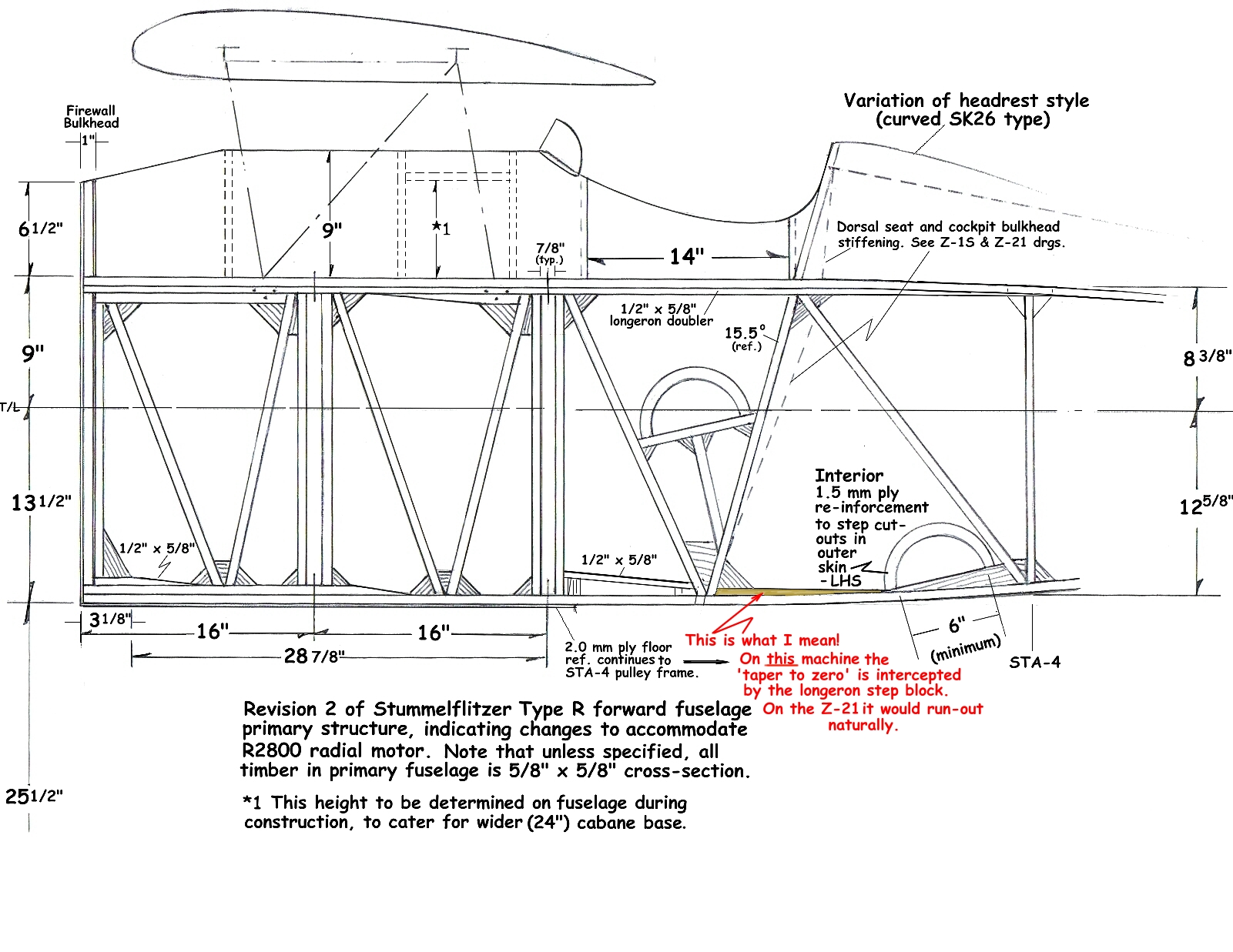
Hi Group,thanks for all the replies-a big help.
Onto another query-I can't find any drawing showing the firewall bow larger than the 1:8 scale firewall drawing itself. Do we just try and scale it off this, or have I missed something?
Adam[East Anglian Flitzers]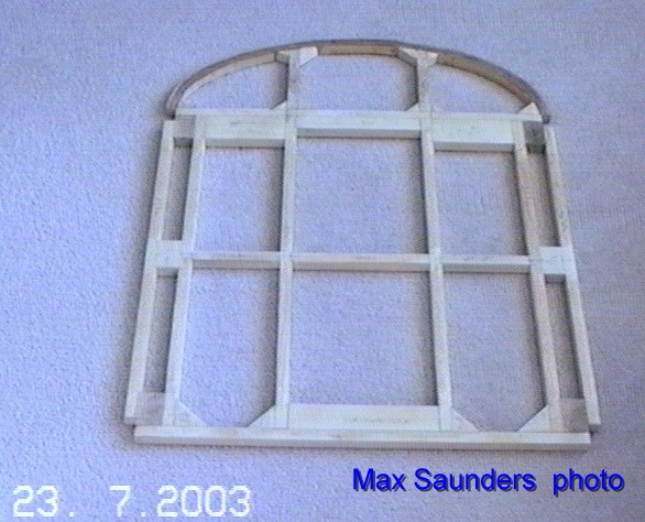
Hi Adam,
The firewall radius is a combination of two radii, with the biggest radius being the one that can be conveniently drawn to encompass the maximum curve achievable within the height and width constraints (this will differ slightly for the wider Z-21A) and the local radius drawn from the horizontal datum to achieve a 180 degree join-line at the longerons. This enables the 2.0 mm plywood decking to be glued 'effortlessly' at the longeron, with a 1.25" ply-overlap joint to provide a strong bond to react the fuel tank loads under -g, and allow the tank straps to be tightened with impunity*.
At STAs 1 and 2, that radius is 11.25", centre displaced downwards from the horizontal datum by 2.875" at the a/c centre-line, this measurement taken from the fuselage cross-member upper surface before the 2.0 mm ply stress tray is fitted or the 2.0mm ply corner plates for the cabane roots (see drg. #Z203, at the cabane) which provides a decking height of 8.375" ~ 8.5" (finished height with 2.0 mm ply added). See the note at right of sheet *"notwithstanding any given radius.... 180 degrees ply overlap, etc., etc.". This provides for the local radii at the longerons to blend with the main radius.
For the firewall lamination radius itself, due to the parallel forward fuselage in plan view, you can use the same major radius, but drop it by a further 1.5" approximately, to achieve the dropped line of the nose in side-elevation at the tank bay. The local radii to achieve the '180 degree' join at the longeron will need to be modified , but these are just convenient blends of angles and curves to provide the best overall solution. If you draw the STA-0 and STA-1 frames in front elevation, superimposed, you will soon arrive at a suitable radius that will accommodate both stations with adjustments for the longeron radii.
Note: although the arc-lengths at the longerons are themselves smaller, each will have a larger radius than the main radius.
Further decking frame profiles are drawn on Z204, and Z400 shows more detail on the tank bay plywood overlap, thus incidentally providing an attractive resultant fuselage 'relief-line feature' in side view.
I hope this all makes sense!
Cheers,
LynnMost of the other Z-Types do show the appropriate radii with a dimension to find the centre, so I guess it was an omission on the Z-21 sheets. However, the simplest solution is to try to draw a single arc to encompass the height and width of the firewall and local decking, and then just blend it at the sides with a french curve to achieve a critical angle close to 180 degrees at this point.
The closer the arch of the firewall is in radius to those of the remaining nose decking laminations, the easier it will be to wrap and glue the 2.0 mm tank bay plywood in place with no visible change of curvature, especially with a high gloss finish (should that be desired) when viewed under a 'harsh light'.
The small detail on this which is shown at right of sheet Z203 might help.
Cheers,
Lynn