
January 21, 2008
Group,
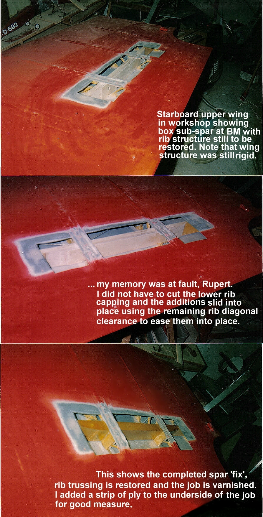
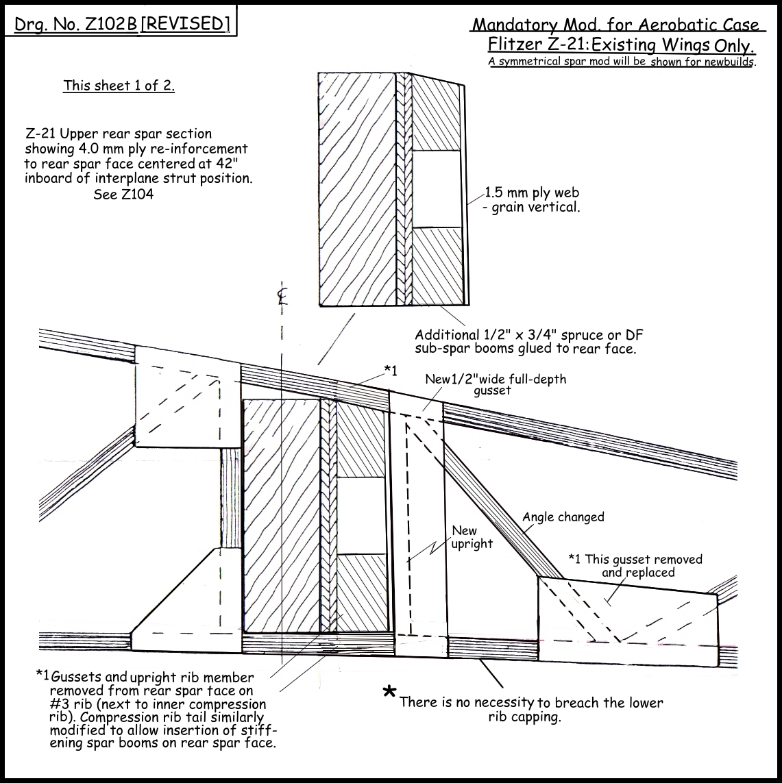
Here are some images of the first 'retro-fix' of the upper wing rear spar which was undertaken in the early 1990s on the prototype Z-1, bringing that aircraft up to the theoretical aerobatic case for the wings. Subsequently the advised mod of 2.0 mm ply backer (further revised to 4.0 mm) has been found to be inadequate for the aerobatic reserve so for existing Flitzers I have created a new drawing, Z102B, which shows this modification. Note that although I have shown the lower rib capping as being cut-away and restored with a scarf joint on that drawing, it is not in fact necessary to do this as the new spar booms can be inserted through the rib structure as shown here, with only one upright and one diagonal being replaced on the inner mainrib and a similar fix being applied to the compression rib tail depending on how this has been constructed.
Best regards,
Lynn
February 1, 2008
Group,
Further to my earlier email showing the upper rear spar fix, here is a further calculation showing that the 4.0 mm ply end tapers should be maintained!
If you can get a power file in to chamfer the tapered boom ends a little (even if this results in a curve to the taper) this will suffice to minimise the vertical edge-riser at the end of the 4.0 mm ply.
In the LAA we need to show compliance with the stress report so it may be necessary to change the boom-ends a little as shown in the attached PDF.
Cheers,
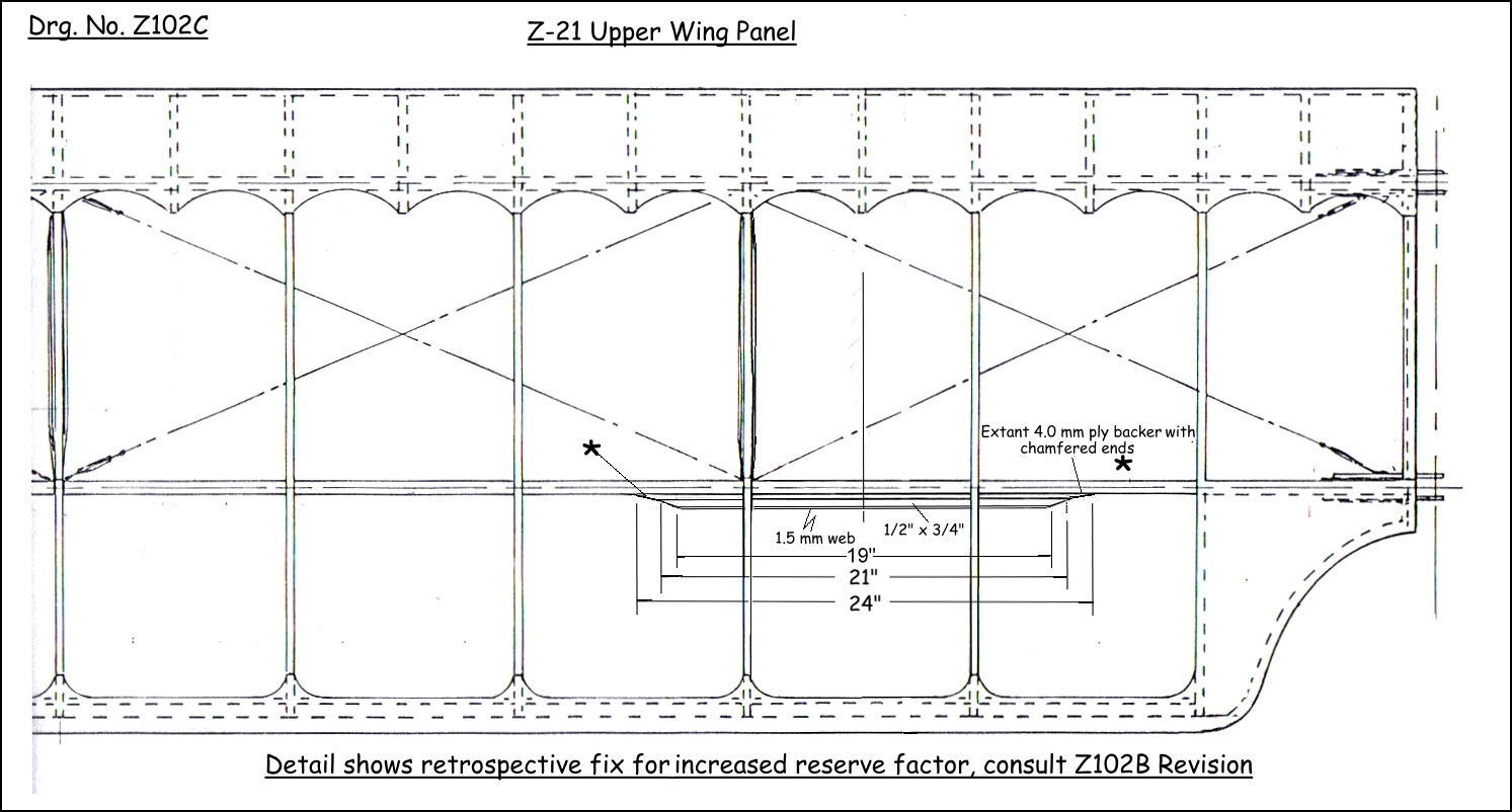
LynnQ: Following receipt of the plan view, just how important is it to restore the chamfers to flat, and make the spars 24"? I have trimmed mine to fit to the edges of the chamfers, 21"! Curses!!!
Oh, and won't there be an abrupt change of strength at the ends of the reinforced section, leaving a virtual weak point? (I'm looking for an excuse to retain the bits I've already made!)
A: Of course a severe cut-off would theoretically create a stress riser, but it's better if the sub-spar booms are longer really. On the new-builds they'll extend 36" on the rear face x 3/8", thick only and the same, but 28" long, butting against the compression rib on the front face. This will create a symmetrical 'I' beam with an 'overshoot' at the compression rib to further reduce a stress riser, both boom sets faced with 1.5 mm ply.
I'm sure your booms will be OK at the length you've cut them, but you could extend the 4.0 mm by adding wedge sections which will increase the basic ply length further each way. This would reduce that 'edge' to the structure. Whatever you do in this regard within reason is going to strengthen the wing spar, and the original 'fix' called for 21" of length anyway - I increased it to 24" as well as doubling the ply to 4.0 mm, but in the event that proved less efficacious than the sub-box arrangement.
On the new build versions I might reduce the boom thicknesses at the extremities in face view as well as in plan, to again reduce the sudden localised stiffness.
Q: - and for those of us who have put ply on both sides of the compression rib tail there is a little more work to do to get sufficient clearance. Then we need to make provision for a ring spanner or a socket to get to the compression rib bolt. Oh well, at least I haven't got any fabric in the way yet. Thinking about the material I have left over, I'm wondering if 7/8 x 1/4 strips, with a 2mm ply web would also add sufficient strength.
A: You don't need to touch the compression rib bolt. The booms will go above and below it. The web can have a hole in it at the bolt position. I don't think that deeper booms without the requisite width will work, they won't provide the 'Z' modulus. Just laminate some bits together. Or use a local timber of adequate strength.
Q: - and if necessary it would be possible to do something on the inside of the spar, butting against the ribs.
A: Yes, but I'd recommend 3/8" booms in that case, as on the 'new build' version - well if you were cutting out the rib material that is. For butting against the two ribs - that would work. I'd rather see 3/8" than 1/4" though. Why not laminate something to 1/2" on the back face anyway?
January 24, 2008
Leute,
Our Leader has decreed that wing spars must be stronger, so I ran into the workshop to do his bidding. Attached is the first stage complete, with the conflicting struts and gussets cleared away. Next stage is making all the parts and extending the 4mm doubler out to at least 24". Those pix will follow soon.
If you have opted for the closed gusseting on the compression tailrib, as I did, you will have great fun cutting the ply away! I used my Dremel with cutting wheel in the end.
Chips von Schmirk
 |
 View from other end. |