May 23, 2007
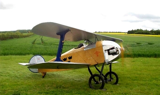
Here's an impression of the Z-4 with the bigger chord and span wings with rounded tips. Although a fabric-covered rear fuselage is under consideration, this adaptation, based on a picture Rupert's Z-21, retains the plywood fuselage, but the cowling is more rounded, similar to the Z-1 prototype's.
Elliptical fin/rudder is used and it has a slightly bigger tailplane than that of the Z-21.
Note the Swedish markings!
Lynn
Blake and Group,
Indeed the Z-1M Meteor Speedwing and the projected Z-4 are not the same.
Further to the growing interest in a microlight version of the Flitzer, the following is based on my interpretation of the ANO regarding the definition of Microlights as of April 2002. The definition allows for a MAUW of 300 kg. for landplanes, or 390 kg. for landplanes which were granted permits to fly prior to January 2003 in the UK.
What I am proposing in the Microlight version of the Flitzer is an adaptation of an existing design, to bring the stalling speed down to 40 mph, ie., a reduction in the power-off stalling speed by less than 2 mph. IAS(!). I believe this can be achieved with a tare weight close to that of the Z-1 prototype, ie. 480 lbs, with a 180 lb. pilot and using 55 lbs. of fuel (even though the regulations allows for a higher weight if we accept that the aeroplane pre-dates Jan 2003 in its original form) using a laden weight of 325 kg. or 715 lbs, which is about the figure at which I have tended to fly the existing aeroplane. The alternative is to create an even bigger wing to reduce the wing loading to 25 kg/sq.metre, but then I think structural weight would be increasing in a no-win situation. Getting the structural weight below 300 kg however would require a much lighter engine if the integrity of the airframe were to be maintained, which could be achieved with a small, geared Rotax, but the appearance would suffer and the 'nostalgic' sound of the siamesed-VW would be lost.
The present plan would be to increase the overall wingspan by only 12", ie. to use a rounded tip which will render the cantilever outer portion of the wing as stiff as possible given the small extension (which is only 6" per side) in combination with a very modest wing chord extension of 2" per panel, ie. from 34" to 36" on the upper wings and from 32" to 34" on the lower. The rounded tip will minimise any additional roll-damping tendency and the curved aileron TE at the tip will not add any appreciable torsional loading at large deflections in conjunction with the new rounded tip. These changes would result in an increase in the W/A from 97'sq. to 108'sq., approx.
The spar cross-sections would remain as they are so as not to increase structural weight, so the T/C ratio would change from 11.6% to about 10%. The aeroplane should be amply strong in the +3.8 G (normal) category for manoeuvring, since microlights are anyway prohibited from performing aerobatics. Note that the interplane strut locations on the Z-21 are already biased further towards the tips than I would have attached them in order to locate these struts on a compression rib. Had compression tubes been fitted, these would have moved the interplane struts 6" further inboard. This situation is advantageous to the slightly extended tip of the proposed 'Z-4'. (NB. the Stummels have shorter wings and deeper spars and are 'ideal' in that respect).
All metal parts would remain identical to those of the Z-21 and the only other change would be the extended tailplane spars to create a bigger tail volume and ensure that the pitch attitude could be held, allowing a high enough AOA for a 'g' break below 40 mph. Whether any advantage might be gained from eliminating the ply skinning of the rear fuselage for fabric, with elongated longeron gussets and diagonal braces with their attendent cluster blocks, is a moot point on such a small aeroplane, and my inclination is just to reduce the ply thickness back there from 1.2 mm to 1.0 mm. instead. In other words do the minimum to alter the structure of the design to comply with my interpretation of the ANO. Geometry, rigging, resulting tail arm within a few % all remain as per the Z-21.
I am attaching a letter which covers the above with a few more details.
Best regards,
Lynn
Chaps,
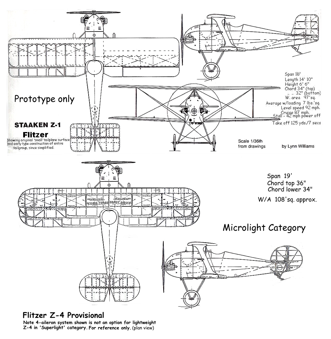
Here is a provisional plan and elevation of the Z-4 Superlight Flitzer.
So far the fin/rudder for the Z-21 Roundtail option is also annotated for the Z-4 Superlight.
The fuselage of the Z-21 is unchanged apart from the fabric-covering to the rear fuselage with a different gussetting arrangement, and the Z-1S headrest option, if requested.
The tailplane is as shown here for appropriate area increase. The wings here show a four-aileron arrangement from the Z-1S Stummelflitzer, but for lightness and simplicity a two-aileron wing arrangement only is recommended. Roll-rate will still be about 100 degrees/sec. I hope that we can reduce the stalling speed to about 40 mph, power off and less than 30 mph. at full power and high AOA. I am considering reducing the wing thickness to approximately a 10% T/C version of the USA 35B (around 85% of the original section thickness) to reduce whetted area and maintain the original spar sizing of the Z-21 and so avoid weight build-up with the increased wing chords. This should provide an amply strong wing provided the weight is firmly controlled. The rounded wing tips will provide the necessary stiffness with the wing area increase and should reduce roll-damping.
Note that for convenience the wings are adapted from those of the Stummeflitzer GA, so that they've been stretched. This gives an erroneous appearance to the rib spacing which will still be pitched at 12": see the upper GA of the Z-1 for reference.
Best regards,
Lynn
 |
 |
February 25, 2008
Group,
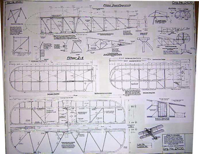
Here's the fuselage, wing and tailplane sheet for the Z-4 Ultralight,Z4100. Note that we are into four figures for drawing identification! :0) This would have been printed today but for a snag at the printing facility, so it has to wait until Thursday.
This drawing supplements the two previous sheets, the Z-4 elliptical fin/rudder drg. and the Stummelflitzer fin and rudder ribs (full size) drawing, whose ribs match those of the Z-4 and which have already been despatched to builders.
Next to come will be the mainrib and outer rib drawings for both wing panels, which are of increased chord but of of slimmer section than the standard USA 35B, based on a smaller % of the ordinates, so maintaining the basic Z-21 spar sections and maintaining 100% commonality of metal fittings, as well as a general arrangement drawing and specification sheet.
This aircraft still needs to be named!
Lynn