
 |
2 | 3 |  |
Hi Group,
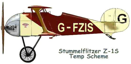
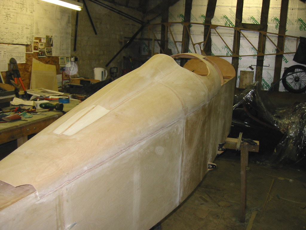
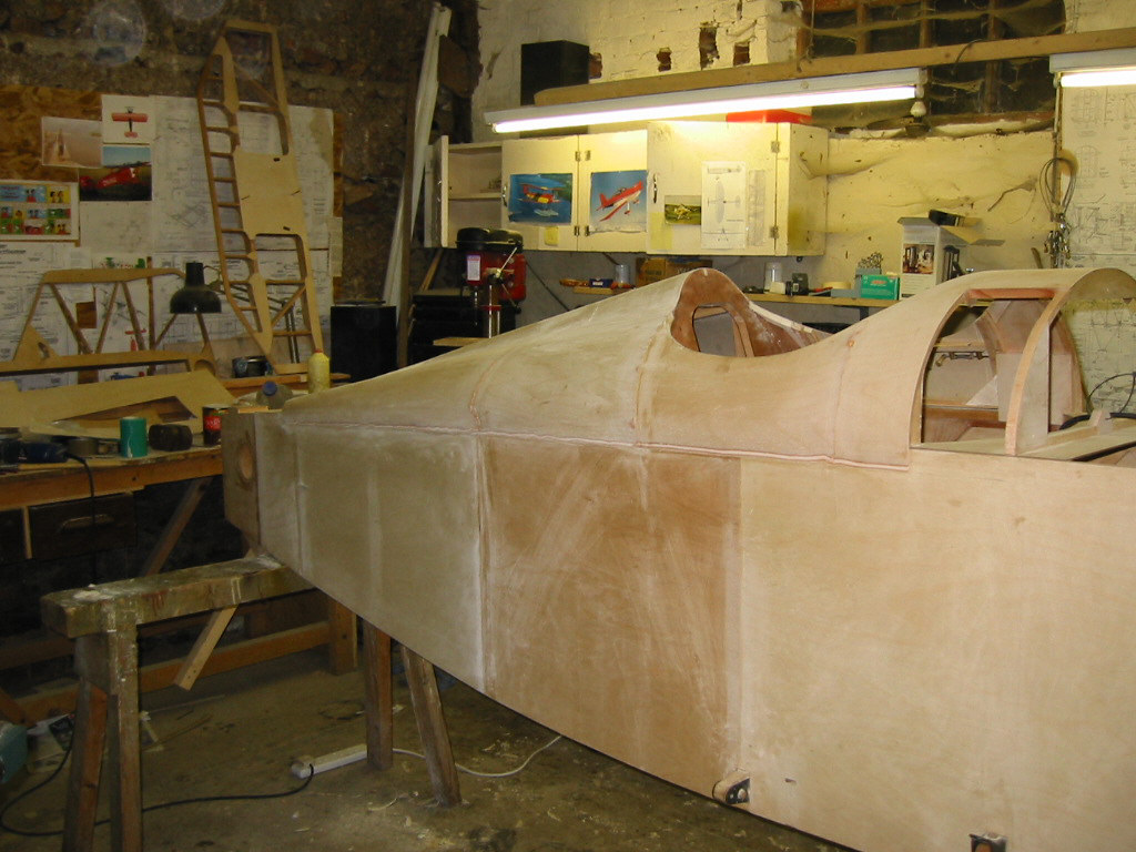
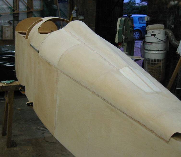
Here are the latest pictures of Vic Long's Z-1 S Stummelflitzer, the first UK example. They'll be sent in two parts due to the file sizes.
Vic and Jeremy's SK26 won an award last year at Kemble for the best part-completed project, but that is on hold at the moment. Vic is concentrating on the Type S for the time being, and his son, Zeb, seen here in one of the pictures, has commenced a Flitzer Goblin.
He is rapidly catching up on Emmanuel in France, who has the most advanced Type S at present. Both Vic and Emmanuel are also well on with the wings.
It looks really great, Vic.
Best regards,
Lynn
 |
 |
 |
 |

June 17, 2005
Dear Lynn,
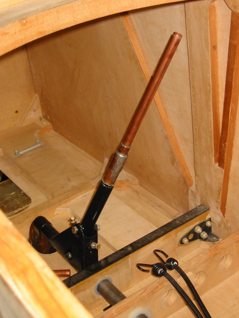
Attached some elevator pictures, also one of the control column. The one I had was cranked, which didn't seem right, so here's an insertable version which has the advantage over the standard in that a thermostatically controlled shut off valve can be installed to control the temperature of the grip.
No snags or fouls; it works very smoothly, but I spent hours on it with bits of string working out how it would run. The strap I mentioned to you on the phone, just in front of the skeg, is due to the slightly modified geometry back there, trying to get the lower longeron curve right for the rudder, and other dimensional issues. To get the angle of the skeg to look good, I had to shorten it a bit, and to maintain the lever arm, had to omit the faired piece just above the skid.
The UFO prog was good, interviews with 80 or 90 yr old scientists who worked on the Nazi developments, then the Russians, eventually the US. According to the documentary, the huge interest in UFO's from outer space in the 50's was sponsered and propagated by the CIA to divert attention. I think Zero Point alludes to that.
All the best, Vic
Hi Groupies,
Here's the latest from Vic Long's #1 UK Z-1 Type S Stummelflitzer project, showing the elevator cable runs and a (temporary) copper control column! The cranked stick that Vic mentions was a feature of all Tony Morris's aeroplanes and is thus also installed on Flitzer Z-21A G-BYYZ. Vic used some of Tony's metal parts from a terminated Type S project that he, Tony, was working on before he unfortunately lost his licence due to a medical anomaly.
Tony evidently enjoyed building the Z-21A, which he completed in 30 months, to then start another Flitzer type almost immediately afterwards. Only a heart trace glitch robbed him of that dream, and we'd probaby have seen a Stummelflitzer flying by now, if he'd carried on with it. Vic is doing a stirling job in progressing the Z-1S however, as may be seen from these pictures.
Best regards,
Lynn
 |
 |
July 29, 2005
Dear Group,
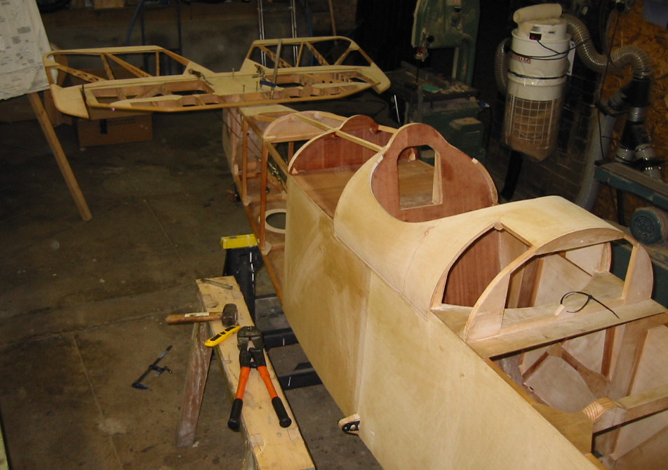
Latest pictures attached of the Z1S rear decking, a phase that has been fairly time consuming. Contrary to the drawings, I covered the 'cheeks' of the luggage locker first, in 1.2mm, then from there back with 1mm in a sngle wrap. It took a while to get the curves of the 3 relevant frames right, but it's worked out well. Mark, I'd suggest the same approach to you, just keep shimming and sanding with a long straight edge till a piece of ply sits well. A slight high on the middle of the 3 frames is preferable to a dip, since the very small complex curve can be worked out. . I think Rupert may have done the single wrap too. Of course the headrest is a Z1S specific item, and was simple after the main deck.
By the way, the engine thread I started has been fascinating; thanks for the various contributions.
Regards to all, Vic
 |
 |
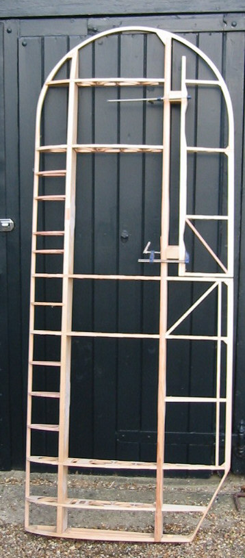
August 7, 2005 - Tail Group
Morning Guys,
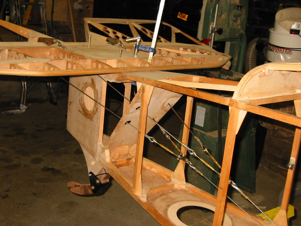
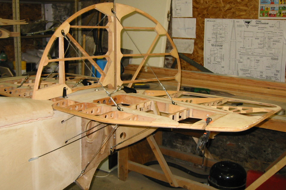
Attached picture of rigged tailgroup for Z1S. Can now sit in cockpit and wiggle everything. Another step forward. By the way, the rudder peddles are hinged on a very expensive extruded aluminium section (�3500) waste piece, which is for a Me 262 tailplane leading edge. The top and bottom skins are joined as in a hinge at this point.
The bracing wires are very stiff and awkward to bend, but a simple peg board made the job very quick and easy.
Good news John, on your progress. It gets much easier once you've started.
Regards, Vic
October 9, 2005
Hi Group,
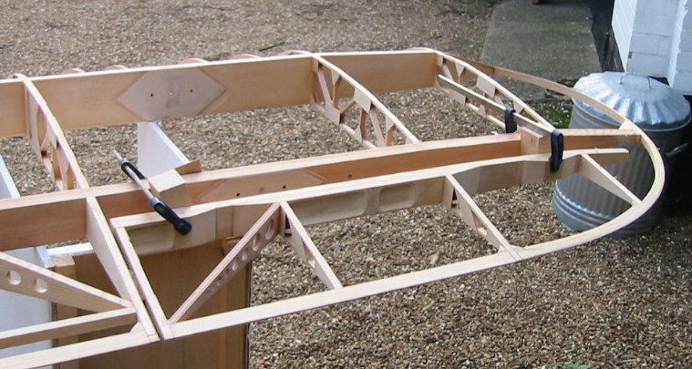
First picture of Vic's Z-1S wing, starboard lower.
Vic, if you receive this via the Group, I tried to email you again this evening, but the message was 'undeliverable'. Your computer is blocking everything I send, even without attachments!
I have sent you the amendment drawing showing the bracket modification for the Stummelflitzer aileron tube-hinges by post. Obviously I am receiving your emails OK.
I made good progress on the hangar this weekend.
Best regards,
Lynn
October 23, 2005 - Wings
Morning Group,
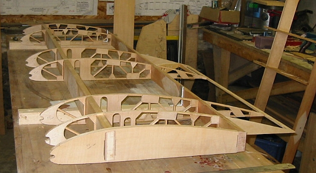
Attached 2 pics of Z1S lower wings. Ailerons ready for gluing up, tip bows laminated so progress should be swift from here on in.
Re. a comment on a post earlier, on Lynn's ability to reel one into his world. He sent me an early drawing of the round tail just for a little 'feedback'. It was such a lovely shape, an looked like a very satisfying piece of laminating, I just I'd see how it looked in wood. I then needed the rest of the tailplane to attach it to, then a fuselage, and as you see, now some wings.
Be careful.
Vic
 |
 |
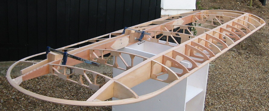
November 8, 2005 - Wings
Dear Lynn,
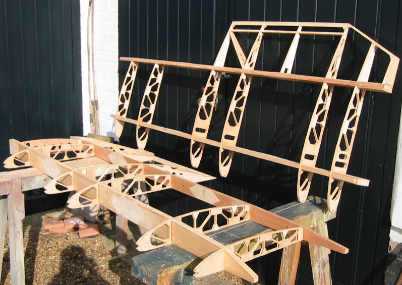
Attached latest wing pictures. Theres quite a swoop up of the trailing edge, about 1/2'', between the outer ribs, but it all checks out as calculated for washout. The drawing shows the aileron as made, but I'm wondering whether to truncate it at the outer rib as it is now, rather than squeezing an extra rib in there. Any thoughts?
Vic
 |
 |
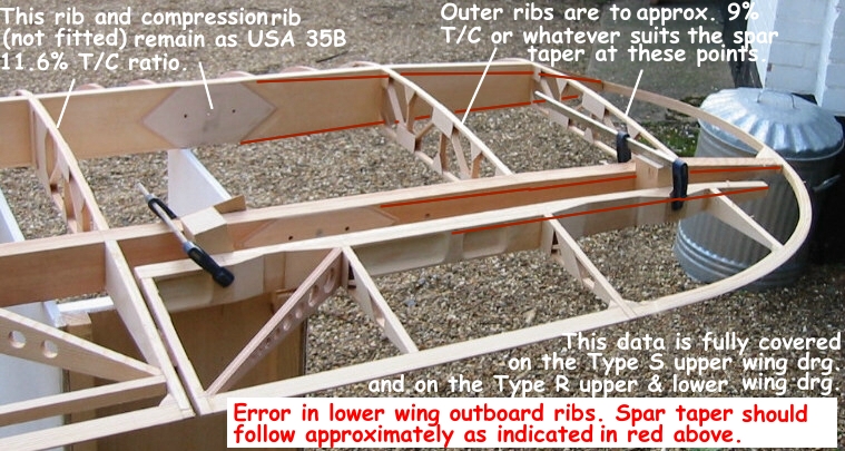
Hi Group,
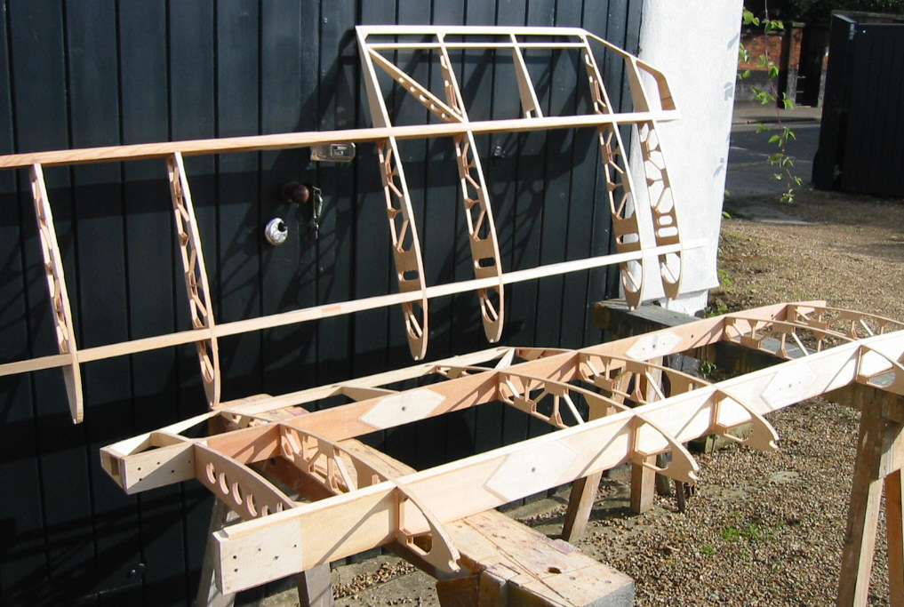
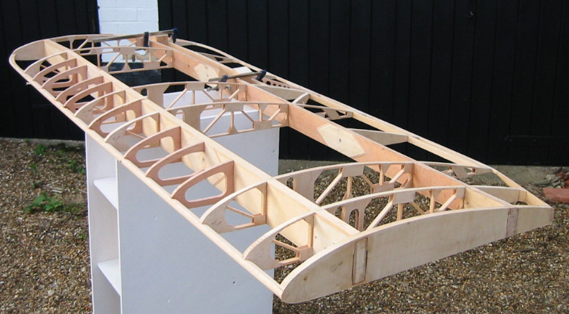
Please note that the 'kinked ' aileron TE, which was bothering me on Vic's Stummelwing, was the result of a misinterpretation of the existing Stummel wing plans. Vic overlooked the detail on the upper wing, which showed that the rib outboard of the compression rib is reduced in thickness, but not chord, and the subsequent rib, next to the tip, being reduced by the same proportion, with a reduced chord, the result of the rounded wing tip. The last few ribs are washed-out progressively, and this aerodynamic twist is built into the rib design. Thus the aileron TE should progress to the tip curve in a gradual climb, from the aileron root to the wing tip, when viewed from behind the wing, and is seen effectively as a straight line, with no 'kick' up.
The detail for this on the Type S upper wing and the Type R, for both wings, is clearly shown on the sheets, but has not been drawn (ie. a full-size rib with the modified incidence and T/C ratio has not been drawn) for the 'S' Type lower wings yet. Emmanuel Parrein made his own drgs. for the lower wing ribs, so I presume these are right.
It is a pity that Vic has to undo some of this wing structure, as it is very well made.
The approximate changes are indicated on the attached photograph.
Regards,
Lynn
November 9, 2005
Morning group,
Was pondering this half the night. Real bummer.
In my defence though, the outer rib as built is reduced 10%, and the reduction of the previous rib is only evident if you measure the spar depth on the upper wing rib drawings. There are no rib drawings for the bottom wing.
Regards,
Vic
|
2 | 3 | |