 |
 |
||||||
| 1 | 2 | 3 | 4 | 5 | 6 | ||
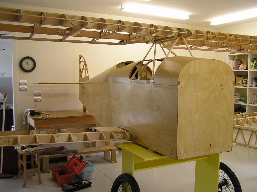
March 22, 2008 - Trial Fit
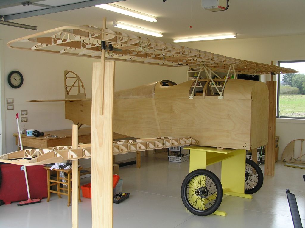
The wings fit !! So that is a major milestone. Needed to get to this point to measure the lengths for the landing and flying wires, and the aileron control cables. I've had the tail group fitted before and the cables for rudder and elevator are all sorted.
I also need to get a smart level with the digital readout to make sure I get everything properly aligned. It is just too hit-and-miss with a conventional level.
I'm not sure about the yellow undercarriage though. I think that has to go.
Brian
 |
 |
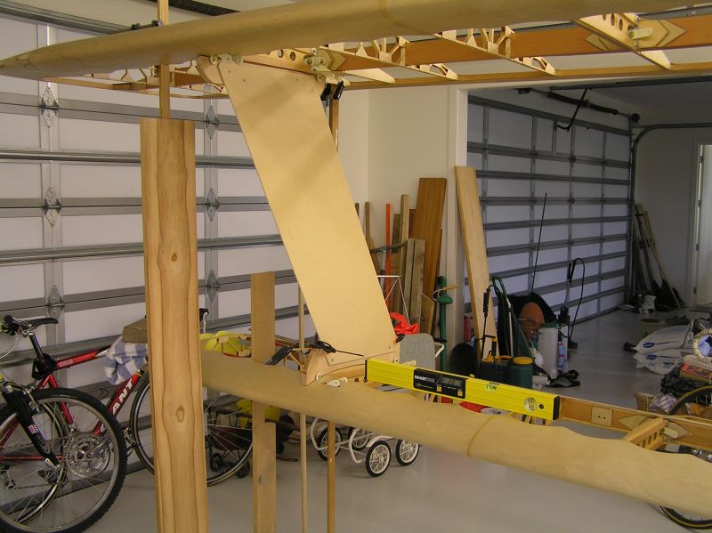
October 4, 2008 - Getting the Angles Right
I haven't seen a description, nor any photos that I can recall, regarding setting up the wings to measure and make the interplane struts. So, with trusty SmartLevel in hand I set about to jig everything up to do the job.
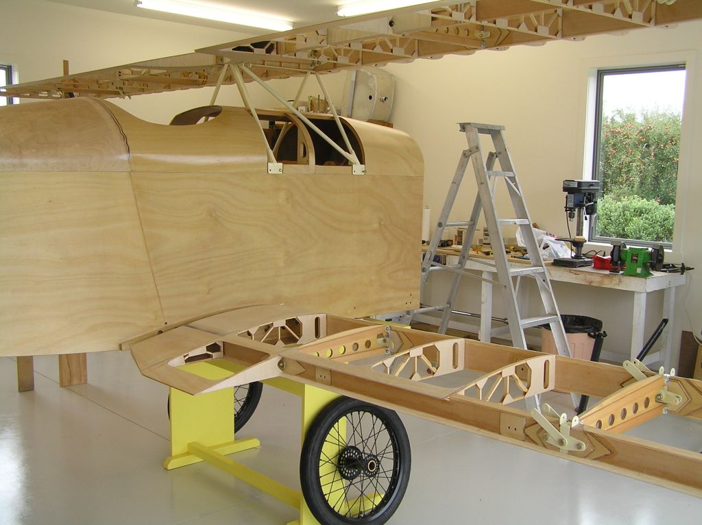
The fuselage was set up first, level across, and roughly in the flying attitude, although this is incidental, and it just worked out that way because of the height of the tables I was using. Wings were then attached. This was done single handed. It is easy to bolt up the lower wings because the tips can rest on the floor as you locate and insert the bolts. Not so easy with the top wings - - balancing them on a ladder. It would be far easier to have had a helper while trying to guide the bolts into position.
Temporary floor struts were clamped into position on each wing and the dihedral was trimmed by adjusting the clamps, and later by using small shims under the struts. Using the digital level made this exercise painless. It was easy to trim the adjustments to achieve precisely 2 deg on the bottom wings and 1 degree on the top.
It would have been useful to fit the landing wires at this point and trim them to hold everything in position, but since part of the reason for this setup is to measure the required lengths to have them made I didn't have that option.
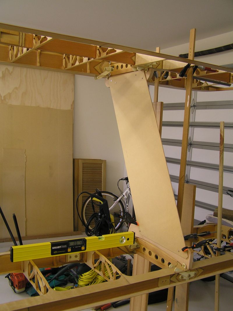
The foot ends of the interplane struts had been roughed out previously, to sit nicely on the wing brackets, and drilled. The drilled holes will need more attention later. The foot bearing points had been set up with some ply scraps glued in place, and a deal of filing to get the seating and the angles right. With these bolted into position, I made a temporary strut from 6mm customwood and screwed this firmly to the upper wing foot.
Now, with some additional struts to the floor I trimmed the washout in each wing for 1 degree at the tip. This process required a number of iterations until I was satisfied that the dihedral was maintained correctly at the same time. Frankly, I can't imagine how fiddly this would have been without using a digital level.
It was interesting to see how much the other end of the temporary strut [on the bottom wing foot] moved around as the washout was adjusted, which illustrated, I think, how critical it seems to get all the angles set up properly before finalising the strut geometry.
With all the angles confirmed - - and the same on both sides of the plane, I screwed the temporary strut to the lower wing foot. Now the whole temporay strut assembly can be removed and the end feet firmly screwed to the work bench, which then becomes the jig for the remainder of the strut construction.
The pictures show the right strut. Does it fit on the other side also. Nope ! but it is close. There are subtle differences in the foot bearing points, and of course the angles on these bearing points are different. I think these differences explain the reason for it not fitting. As an aside, I measured the height of the wing tips from the floor and was agreeably surprised. Also did a number of other rigging checks and was happy with the results.
Brian
 |
 |
October 8, 2008 - One of a Pair
Turning the template into a real strut. In fact a brace of struts. Interestingly, the struts do not match hole for hole, but they are not that far out. Swapping them around I can get three of the holes to align but not the 4th. The differences that may exist at the wing bolts are magnified many times out at the strut positions so I suppose it is not surprising. Oh well, they are now well and truly cast in stone - - I mean epoxy, so it will be interesting to see what trimming needs to be done for level flight.
Brian
 |
|
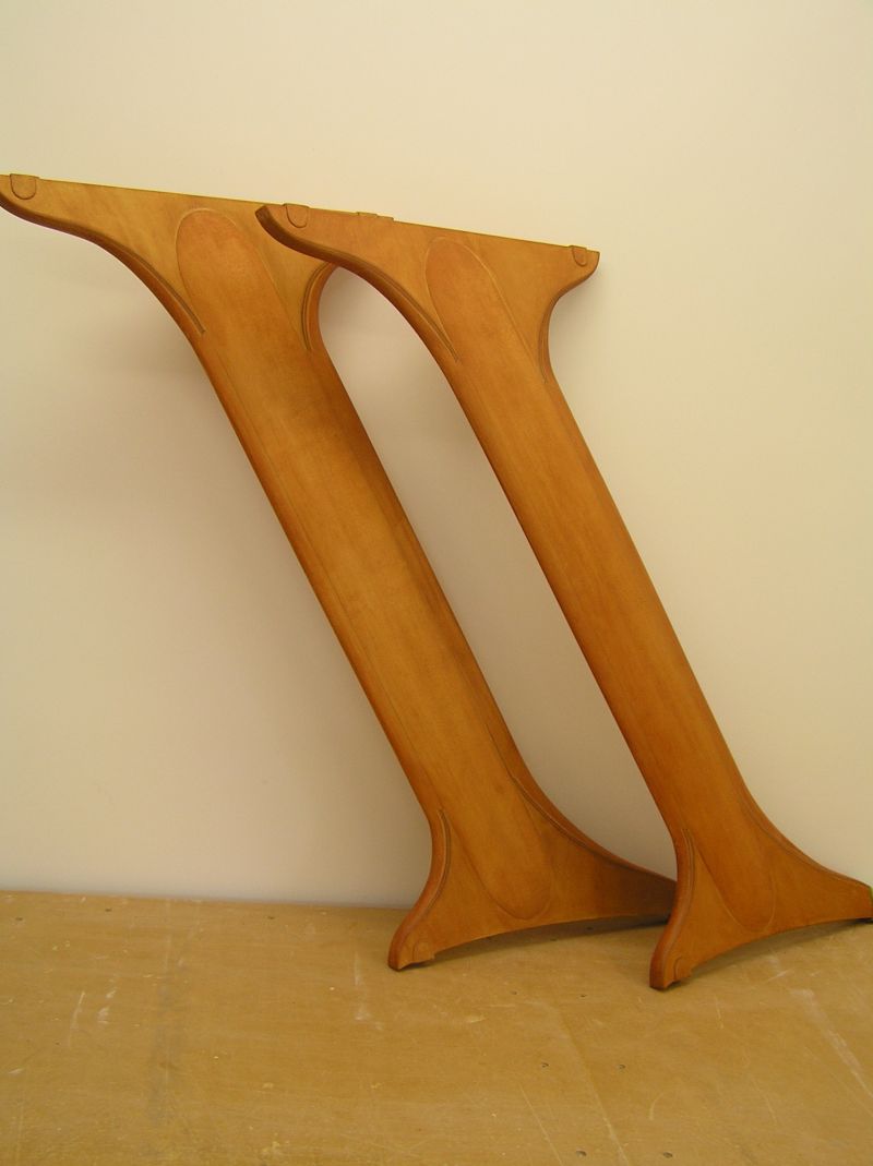
November 16, 2008 - Shaping Other Wooden Bits
It's raining today so I am taking a break from planting trees and hedges on the Flitzer field. Up to my knees in wood shavings and sawdust instead. While these are the last two wooden parts to be made they are taking a while longer than anticipated. The basic construction was Ok, just one step after another to glue up all the parts, but the work required to shape them is something else, and this is after getting the basic shape of the outside cheeks done before gluing them in place.
One strut is now completed, ready to stain. I've tried a variety of tools to try to make the job easier, and while everything is good for some aspect, there is still a lot of elbow work. Tried using the band saw and a hand saw to rough out the LE and TE sections. A disc sander - - used with caution - - - helps with some basic shaping. A small block plane works well in places. Wood rasps and files of various sizes help, and then sandpaper and elbow grease - - - phew !!
The plan is to stain these and see what they look like. If there is not too many scratches nor excess glue then they will be clear finished with polyurathane. If they look a bit ugly, then they will be painted.
Brian
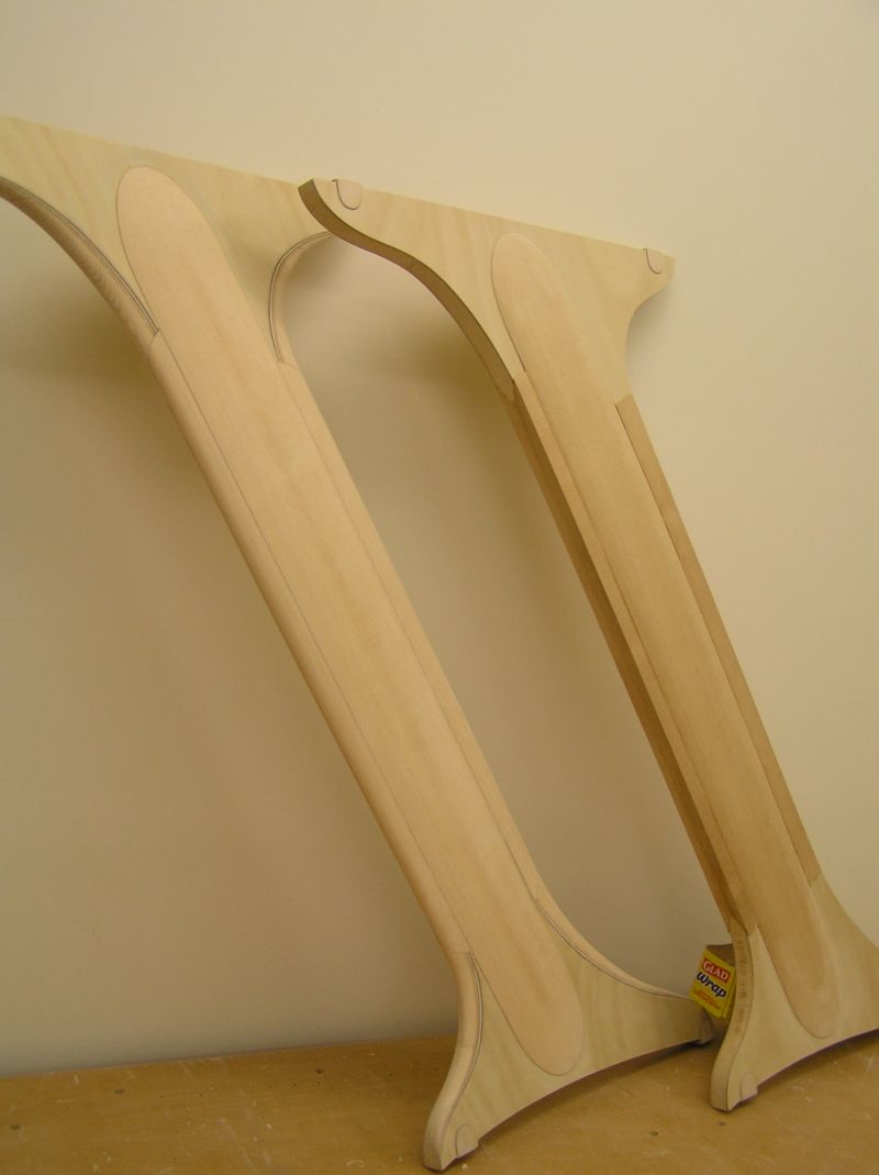
November 18, 2008 - A Matched Pair
I persevered last night until I had both struts properly shaped. Persevere being the right word ! Knee deep in shavings, covered in sanding dust, and it will take me a week to clean up the workshop. I'm pleased with the result though.
Applied the stain today to check out the colour and the finish. I'm pleased with that too, so there is the first element of my colour scheme decided. The same stain was also used in the cockpit area.
So all the woodwork is now complete - - I think. Onto the next phase.
Brian
June 7, 2009 - Brian's provisional colour scheme
Group,
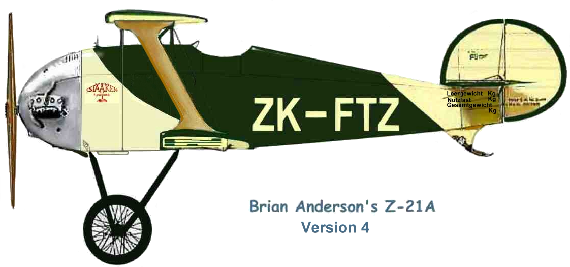
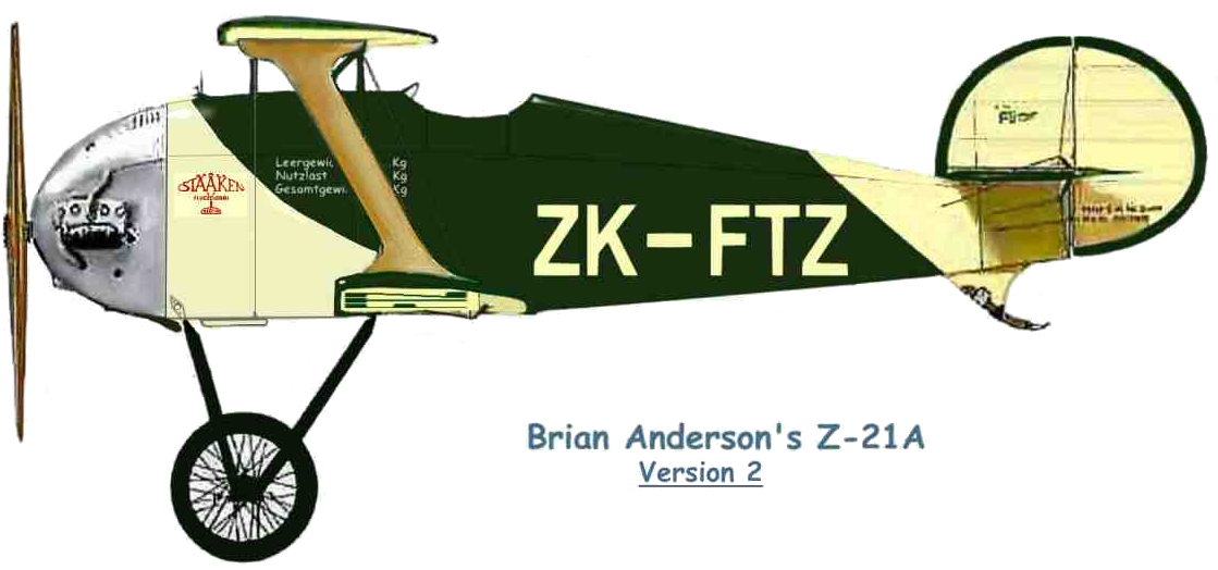
Brian Anderson will soon be ready to spray the colour on his Flitzer Z-21A Roundtail.
His preference was for a very dark green (perhaps British Racing Green) fuselage with very light cream trim, flying and tail surfaces.
This is the second version of the scheme I'd suggested to him, which includes the Stummelflitzer 'aerobatic' style colour divisions to the fuselage although the wings will be plain cream (without upper wing chevrons). The dark green edging to the wings and tail may not actually feature but I do suggest full-span registration lettering on both upper and lower wings in dark green, to break up what would otherwise be a bland panel colour and provide authentic 1920s styling and protocol.
The touch of red in the Staaken logo accents the scheme along with the natural varnished struts and propeller and the Flitzer logo appears in green on the fin. Tare, payload and gross weights appear on the LHS fuselage below the cabane. The complete undercarriage and wheels are shown utilitarian black and the cowlings ar polished aluminium.
This, as far as I know, is how his Flitzer will appear.
Cheers,
Lynn
June 7, 2009 - Brian's provisional colour scheme
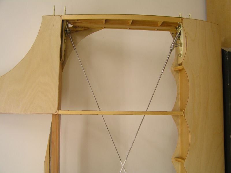
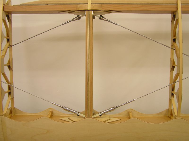
"soon be ready" is a relative term. I've been practicing covering and have done all the small pieces, so now it is on to the wings.
This is a view of the top right wing immediately before covering showing an alternative drag/anti drag wire system. The turnbuckles are made by Ronstan. Wires are 1/8 1x19 SS. Where the wires cross - - - and at that point they just touch - - I have taped them with leucoplast and tied them with waxed rib stiching thread. The leucoplast is als used on the rib cappings for antichaffe.
It was interesting asking lots of people who ought to be knowlegable, about the tension in the wires. The consensus seems to be a "healthy twang". I was able to check mine using a tensiometer, and I found that it was possible to tension them evenly just by twanging and listening to the pitch of the note. Turns out that the resulting tension is about 150 lbs or so.
Brian
 |
 |
|
|
||||||
| 1 | 2 | 3 | 4 | 5 | 6 | ||