Again, the following is not definitive, just my way.
Those of you who were weaned on Keil Kraft (colonials could maybe read Guillow's for that) will remember how one would often build the first fuselage side over the plan after covering it in greaseproof paper or rubbing candle wax into the paper at the joint areas to aid removal (yes, I really am that old). The second side was then built over the first with pins on each side of the members to hold the alignment.
We all know that a Flitzer is only a big model (indeed, some models now are larger than a Flitzer).
| 1 | Draw your fuselage side on top of the bench. |
| 2 | Use polythene or wide cellotape to cover the joint areas (I am pretty sure that a Flitzer hasn’t been test flown with a workbench stuck to one side so you will be breaking new ground if you are not pretty thorough with the protection) |
| 3 | Lay down the upper and lower longerons, screw small blocks to the bench at appropriate positions. Fit the longeron doublers. |
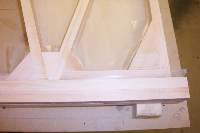
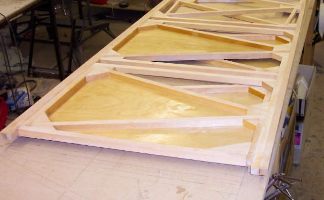
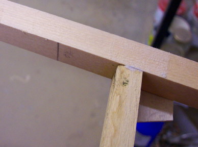
| 4 | Mark, cut and fit (the 12" sanding disc is indispensable yet again) the upright members but make two sets of them, one for this side and one for the next. The second set can be very easily made accurately by placing the pattern member over a stock length and scribing the stock piece using a sharp modelling knife. Cut over size by about 1/16” and sand away up to the scribe mark. I added temporary vertical braces just to the rear of the sternpost position. These will be removed, along with the excess longeron, when the sternpost is fitted. These may be totally unnecessary but I wanted to ensure that the structure maintained its correct shape as the sternpost was fitted. The longerons are clearly marked at their overall lengths for reference. |
| 5 | The diagonals are fitted in the same way after the uprights have been glued in place. |
| 6 | Fit all gusset blockings, again making a second set (it’s a good idea to mark as some will only be slightly different to others). |
| 7 | When all dry run a sanding block over the joint areas to remove any excess adhesive and take out any slight irregularities in material thicknesses. |
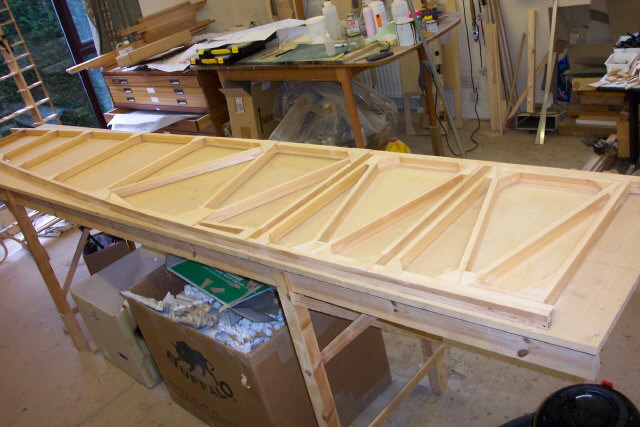
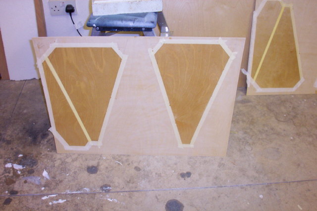
| 8 | Add all internal ply sheeting and gussets, and you’ve guessed it, making a second set. |
| 9 | When set, remove from board, turn over and sand the joints on this face. When satisfied, apply cellotape to cover glue lines. |
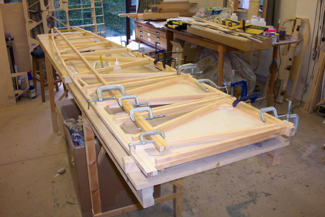
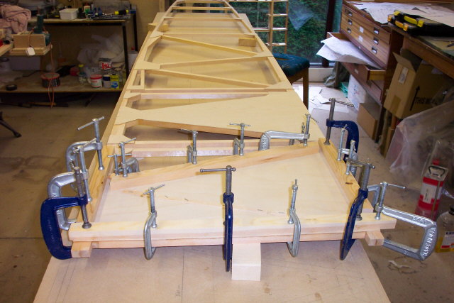
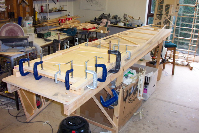
| 10 | Using blocks of the same thickness (about 2" is ideal) block the side off the workbench in several places to allow the use of G clamps. |
| 11 | Now build the second side over the first to exactly the same stage. The beauty of this method is that it should be impossible to build two fuselage sides of the same hand! |
| 12 | Fit the forward outer skins and accurately mask the areas that will be covered up in order to varnish them. Varnish the inner ply areas that will be covered up and fix the outer skins. Some outer sheeting may be attached at this stage toward the rear of the sides but Lynn advises leaving the area of maximum curvature around the cockpit until the fuselage is built. It is also wise to leave the rearmost two bays until after the skeg, and its associated structure, is completed. |